Sunday, March 31, 2013
Pump it up Mp3 Booster
But first we have to build this booster! The small battery-powered players have an output signal that is more than sufficient to drive a set of 32 Ohm headphones. You’ll often find that with an output of 1mW the sound pressure level (SPL) produced can reach up to 90 dB. This would be sufficient to cause permanent damage to your hearing after only one hour! The maximum output voltage will then be around 200mV. This, however, is insufficient to fully drive a power amplifier. For this you’ll need an extra circuit that boosts the output voltage.
Power amps usually require 1 V for maximum output, hence the signal has to be amplified by a factor of five. We will also have to bear in mind that quieter recordings may need to be amplified even more. We’ve used a simple method here to select the gain, which avoids the use of potentiometers. After all, the MP3 player already has its own volume control. We decided to have two gain settings on the booster, one of three times and the other ten times. Amplifiers IC1A and IC1B (for the right and left channels) are housed in a single package, a TS922IN.
The output signal of the MP3 player is fed via a stereo cable and socket K1 to the inputs of the amplifiers. The gain depends on the relationship between resistors R2 and R1 (R6 and R5 for the other channel) and is equal to ten times. When you add jumper JP1 (JP2), resistor R3 (R7) will be connected in parallel with the negative feedback resistor R1 (R6), which causes the gain to be reduced to about three. When you start using the booster you can decide which gain setting works best for you.
Circuit diagram:
The resistors (R4 and R8) effectively isolate the output of the booster from the parasitic capacitance of the output cable. They also protect the booster outputs from short circuits. We’ve used a TS922IN opamp in this booster because it can operate at very low supply voltages (the maximum is only 12 V!), but can still output a reasonable current (80 mA max.). For the supply we’ve used rechargeable batteries (e.g. NiCd or NiMH cells) so that we don’t need a mains supply.
To keep the number of cells required as small as possible, we’ve chosen a supply voltage of 5 volt; this can be supplied by four rechargeable batteries. It is also possible to use four ordinary, non-rechargeable batteries; it’s true that the supply voltage then becomes a bit higher (6 Volts), but that won’t cause any harm. Since we’ve used a symmetrical supply for the booster (2 x 2 batteries), it will be easiest if you use two separate battery holders, each with two AA cells. The two holders are connected in series.
Make sure that the batteries are connected the right way round; the positive of one always has to be connected to the negative of the next. This also applies to the connection between the two battery holders. S1A/B is a double pole switch, which is used to turn both halves of the battery supply on or off simultaneously. If you can’t find the (dual) opamp we’ve used (or an equivalent), you could always use standard opamps such as the NE5532, TL082 or TL072. These do need a higher supply voltage to operate properly. In these cases you should use two 9 V batteries and replace resistor R9 with a 15 kΩ one.
Do take care when you connect the circuit to your power amplifier because the output signal can be a lot larger and you could overload the power amplifier. (Although you’re more likely to damage the loudspeakers, rather than the amplifier!) (Please note that these two 9 V batteries can’t be used as a supply for the TS922IN!) In our circuit we’ve used a stereo jack socket for the input and phono sockets for the output because these are the most compatible with MP3 players and power amplifiers respectively. If you wanted to, you could solder shielded cables directly to the circuit instead, with the correct plugs on the ends. You’ll never find yourself without the correct connection leads in that case!
How to Make a Simple 12 Volt LED Lantern Circuit


USB Operated Home Appliances Cicuit
When turning a computer on and off, various peripherals (such as printers, screen, scanner, etc.) often have to be turned on and off as well. By using the 5-V supply voltage from the USB interface on the PC, all these peripherals can easily be switched on and off at the same time as the PC. This principle can also be used with other appliances that have a USB interface (such as modern TVs and radios). This so-called ‘USB-standby-killer’ can be realized with just 5 components. The USB output voltage provides for the activation of the triac opto-driver (MOC3043) which has zero-crossing detection. This, in turn, drives the TRIAC, type BT126.
Circuit diagram:

USB Operated Home Appliances Circuit Diagram
The circuit shown is used by the author for switching loads with a total power of about 150 W and is protected with a 1-A fuse. The circuit can easily handle much larger loads however. In that case and/or when using a very inductive load a so-called snubber network is required across the triac. The value of the fuse will also need to be changed as appropriate. The circuit can easily be built into a mains multi-way powerboard. Make sure you have good isolation between the USB and mains sections.
Source : www.extremecircuits.net
Mech Tech Notes Solid Mechanics

Aircraft Mechanics Fix Airplane Components Such As This Engine.

57 Bombers And Recon Aircraft Were Builtby Aircraft Mechanic Inc.

How To Start An Aircraft Mechanic School Ehow Com.
Mech 353 Tech Notes Solid Mechanics.

Mit Einem Einziehfahrwerk Von Yellow Aircraft Die Mechanik.

Aircraft Mechanic Schools In New York My A And P License.

Technical English Training For Aircraft Mechanics Holland.

Type D 1 Redskin Jacket Aircraft Mechanic S Type D 1 Als Simple Warme.

An Abstracted Aircraft Wing Illustrating The Connections Between The.

Proud Aircraft Mechanic Pins From Zazzle Com.
Standard Plug Wiring Diagrampageford Truck

Standard Seven Way Plug Wiring Diagram Page 2 Ford Truck.
Heavy Metal Photos Trailer Light Diagram.

Wiring Diagram For Bumper Pull Dump Trailers And Roll Off Dump.

Trailer Pulling Information.

Axle Trailer Axles And Running Gear Components Trailer Plug Wiring.

Generic Diagram Of Trailer Wiring.

Trailer Wiring Connector Diagrams For 6 7 Conductor Plugs.

Wiring Diagram For Trailers Caravans.

Trailer Circuit Wiring.

Pin S Type Caravan Wiring Uk Trailer Parts.
Saturday, March 30, 2013
MOSFET IRF 350 as Power Follower

If the value of the potentiometer is 5 kOhm then the high frequency limit will be about 70 kHz. The power follower can be connected directly to the output of CD player, and for reduction of volume potentiometer 5 kOhm can be used.
Normally, the thermal coefficient of zener voltage of 3V type is negative, and so is Ube voltage of the Darlington transistor. As Ube is reduced by -2mV/°C, zener voltage also goes down with increasing temperature inside a box (but the zener is not on the heat sink of the MOSFET and should not be). In fact there was a fluctuation of 40mA at 2A constant current, from my point of view it is negligible. Of course the heat sink for T1 and T2 should be better than 0.5°C/W for each transistor, so four such heat sinks are needed for stereo.
Voltage Levels Control Relays
Circuit diagram:
Nearly all current consumed by the circuit goes on account of the relay coils, so depending on your relays a pretty hefty power supply of up to 500 mA may be required. When dimensioning the ladder network to create the desired switching levels, it is good to remember that the 741 will not operate very well with input voltages below 1.5 V or above 10.5 V, while voltage levels outside the supply range (i.e., negative or above +12 V) are out of the question. If you do need a switching level in the range 0-1.5 V, consider using an LM324, which contains four opamps in one package. For the high side of the range (10.5 to 12 V), a TL084 or a ‘rail-to-rail’ opamp like the TS924 is required. However, the TS924 cannot be used with supply voltages above 12 V.
12 volt DC Power Supply from USB port
Description :
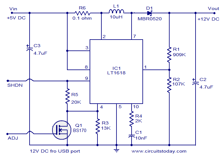
Using this circuit we can convert 5V DC from the computer USB port to 12V DC and a circuit like this will find a lot of application in USB powered systems. The heart of this circuit is IC LT1618 which is a constant current, constant voltage boost converter. The IC has a wide input voltage range of 1.8 to 18V DC and output voltage can be up to 35V DC.

- C2 and C3 must be rated at least 15V.
- Less than 0.3V at the shutdown pin will shutdown the IC.
- Output voltage is governed by the following equation R1 = R2 ( (Vout /1.263V) -1).
Other Circuits Related to Power
Solar Panel Wiring Diagram Data Sheet
Friday, March 29, 2013
BMW E12 L Jetronic Fuel Injection Systems Schematic Diagram
The L-Jetronic System – Control Unit (ECU) takes sensor information such as AFM flow and temperature, Engine RPM (from ignition), Warm up information (from coolant temperature sensor), Throttle mode (idle and WOT switches), O2 sensor in Lambda systems. Then calculates opening duration of injectors. This ‘map’ is hardwired into system (there’s no chip available to modify).
Get detail information about BMW E12 L-Jetronic Fuel Injection Systems Schematic Diagram here – free download PDF file.
Four in One Burglar Alarm

Rj61 Wiring Color Code Pinout Diagramcircuit Schematic

Ethernet Stp Outdoor Ethernet Cable 1000ft Cat5e 568b Wiring.

Infrastructure Wiring Block Diagram Show Ing.

Howstuffworks How Ethernet Works.

Rm4200d Ethernet Wiring Example3.

The Compass Derose Guide To Ethernet Computer Network Wiring.

How To Guide Creating Cat 5 Utp Ethernet Crossover Cable How To.

How To Make A Rj45 Cable Tester.

Rj61 Wiring Color Code And Pinout Diagram Circuit Schematic.

Ethernet Cables By Karl Shoemaker Ak2o.

Terminating Wall Plates Structured Home Wiring.
Thursday, March 28, 2013
Simple RF Detector For 2M
 Assuming that a 10-inch telescopic antenna is used, the RF level scale set up for the LEDs is as follows: When all LEDs light, the (optional) UM66 sound/melody generator chip (IC1) is also actuated and supplies an audible alarm. By changing the values of zener diodes D2, D4, D6 and D8, the step size and span of the instrument may be changed as required. For operation in other ham or PMR bands, simply change the resonant network C1-L1. As an example, a 5-watt handheld transceiver fitted with a half-wave telescopic antenna (G=3.5dBd), will produce an ERP (effective radiated power) of almost 10 watts and an e.m.f. of more than 8 volts close to your head.
 Inductor L1 consists of 2.5 turns of 20SWG (approx. 1mm dia) enameled copper wire. The inside diameter is about 7mm and no core is used. The associated trimmer capacitor C1 is tuned for the highest number of LEDs to light at a relatively low fieldstrength put up by a 2-m transceiver transmitting at 145 MHz. The tester is powered by a 9-V battery and draws about 15mA when all LEDs are on. It should be enclosed in a metal case.
FM Transmitter Breadboard Layout

FM Transmitter Breadboard Layout
Thermostat Delay Relay Timer Circuit
The circuit given below describes a time delay relay system which is used for keeping a hot air blower working under a specifically programmed timing sequence. The idea was requested by Mr. Doug Shadix, lets learn more:
Hi Swagatam,
Looks like you know your stuff when it comes to these timer circuits, this one is a little out there but dont believe it is out of your knowledge.
This is a replacement part for an old Bryant furnace 822 relay. What is needed is a circuit that will get a 24VAC supply when the thermostat kicks in, it will have to have a 45 second delay before triggering a relay that powers the 1/3HP blower motor, the motor needs to run for 45 seconds after the voltage is shut off via the thermostat. Im sure that there is a more efficient circuit other than the 822 relay to do the job, especially when you take cost into the equation.
Once the thermostat kicks in it sends 24VAC thru the limit switch(as long as its not tripped from an overheat), then thru the pilot lights thermo coupler (providing that the pilot is lit)then applies it to the timer/relay. Once the thermostat kicks out the voltage goes to zero across all components.
Yes, the process would have to repeat each time the thermostat kicks the furnace on.
I was orginaly looking at the 556 timer chip to see if it would be able to serve the dual delay, but looking to you for the best way to get it done.
The Design:
The circuit shown below will respond exactly as per the requested specs. The entire functioning can be understood with the the following points:
When the thermostat "kicks in", the 24V AC is applied across D1 and ground of the circuit. The 24VAC gets rectified through D1/C1 and passes through R2 to reach the junction of R3 and D3.
Since initially C2 is in a discharged state the supply gets grounded via D3 and C2.
However as C2 starts charging up, after a predetermined time (45 seconds) set by the values of R2/C2, the voltage across C2 reaches about 1.4V which becomes sufficient to trigger T1.
T1 conducts and so does T2, pulling the relay into action.
The blower connected to the relay contacts initiates.
After some specified time the thermostat switches OFF.
When this happens, the voltage at the cathode of D1 becomes zero which makes D2 forward biased. such that The instantaneous voltage at the collector of T2 instantly passes via C3, D2 and retains the conduction of T1.
The above situation inhibits the circuit and the relay from switching OFF even after the thermostat has switched OFF.
However now C3 start charging up, and after some predetermined time (45 seconds) set by the value of C3/R6, it gets fully charged and shuts off the base bias to T1.....the circuit and the relay also shut off....until the thermostat "kicks back" again to repeat the procedure.

Parts List for the proposed timer delay/relay circuit idea
R1 = 100K
R2 = may be replaced with a 1M preset
R3,R4,R5 = 10K
R6 = may be replaced by a 100K preset
D1----D5 = 1N4007
C1,C2 = 100uF/50V
C3 = 220uF/25V
T1 = BC547
T2 = as per the relay coil current
Under Voltage Lockout for Buck Circuit Using LM2575

In some applications it is desirable to keep the regulator off until the input voltage reaches a certain threshold. These circuits keep the regulator off until the input voltage reaches a predetermined level.
VTH ≈ VZ1 + 2VBE (Q1)
1999 Chevrolet Chevy 1500 Pu V6 Wiring Diagram
 |
| 1999 Chevrolet Chevy 1500 Pu V6 Wiring Diagram |
Wednesday, March 27, 2013
Kapanadze Free Energy Generator Schematics
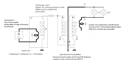
Kapanadze Free Energy Generator Schematics


