Showing posts with label 12. Show all posts
Showing posts with label 12. Show all posts
Thursday, January 9, 2014
12 V Glow Plug Converter
Most small internal-combustion engines commonly used in the model-building world use glow plugs for starting. Unfortunately, glow plugs have an operating voltage of 1.5 V, while fuel pumps, starter motors, chargers and the like generally run on 12 V. This means that a separate battery is always needed to power the glow plug. The standard solution is to use an additional 2-V lead storage battery, with a power diode in series to reduce the voltage by approximately 0.5 V. However, this has the annoying consequence that more than 30 percent of the energy is dissipated in the diode. Naturally, this is far from being efficient.
12-V Glow Plug Converter Circuit diagram :

The converter presented here allows glow plugs to be powered from the 12-V storage battery that is usually used for fuelling, charging, starting and so on. A car battery can also be used as a power source. Furthermore, this circuit is con-siderably more efficient than the approach of using a 2-V battery with a series power diode.
The heart of the DC/DC converter is IC1, a MAX 1627. The converter works according to the well-known step-down principle, using a coil and an electrolytic capacitor. Here the switching stage is not integrated into the IC, so we are free to select a FET according to the desired current level. In this case, we have selected a 2SJ349 (T1), but any other type of logic-level FET with a low value of RDSonwould also be satisfactory. Of course, the FET must be able to handle the required high currents.
Diode D1 is a fast Schottky diode, which must be rated to handle the charging currents for C2 and C3. This diode must also be a fairly hefty type. The internal resistances of coil L1 and capacitors C2 and C3 must be as low as possible. This ensures efficient conversion and prevents the components from becoming too warm.
The resistor network R2/R3 causes 87 percent of the output voltage to be applied to the FB pin of IC1. This means that an output voltage of 1.5 V will cause a voltage of approximately 1.3 V to be present at the FB pin. The IC always tries to drive the switching stage such that it ‘sees’ a voltage of 1.3 V on the FB input. If desired, a different output voltage can be provided by modifying the values of R2 and R3.
When assembling the circuit, ensure that C5 and C1 are placed as close as possible to IC1, and use sufficiently heavy wiring between the 12-V input and the 1-5-V output, since large cur-rents flow in this part of the circuit. A glow plug can easily draw around 5 A, and the charging current flowing through the coil and into C2 and C3 is a lot higher than this!
Source : http://www.ecircuitslab.com/2012/07/12-v-glow-plug-converter.html

Monday, July 29, 2013
How to Build 12 Volt DC Fluorescent Lamp
A number of people have been unable to find the transformer needed for the Black Light project, so I looked around to see if I could find a fluorescent lamp driver that does not require any special components. I finally found one in Electronics Now. Here it is. It uses a normal 120 to 6V stepdown transformer in reverse to step 12V to about 350V to drive a lamp without the need to warm the filaments.
 Parts:
C1 100uf 25V Electrolytic Capacitor
C2,C3 0.01uf 25V Ceramic Disc Capacitor
C4 0.01uf 1KV Ceramic Disc Capacitor
R1 1K 1/4W Resistor
R2 2.7K 1/4W Resistor
Q1 IRF510 MOSFET
U1 TLC555 Timer IC
T1 6V 300mA Transformer
LAMP 4W Fluorescent Lamp
MISC Board, Wire, Heatsink For Q1
Notes:
 Parts:
C1 100uf 25V Electrolytic Capacitor
C2,C3 0.01uf 25V Ceramic Disc Capacitor
C4 0.01uf 1KV Ceramic Disc Capacitor
R1 1K 1/4W Resistor
R2 2.7K 1/4W Resistor
Q1 IRF510 MOSFET
U1 TLC555 Timer IC
T1 6V 300mA Transformer
LAMP 4W Fluorescent Lamp
MISC Board, Wire, Heatsink For Q1
Notes:
- Q1 must be installed on a heat sink.
- A 240V to 10V transformer will work better then the one in the parts list. The problem is that they are hard to find.
- This circuit can give a nasty (but not too dangerous) shock. Be careful around the output leads.
Friday, May 17, 2013
12 Volt car Battery Monitor Circuit
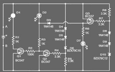 12 Volt car Battery Monitor Circuit
This circuit can be used to monitor the voltage level of a car battery. When the battery voltage is 11.5V or less the transistor Q1 is on and D1 glowing.When LED battery voltage is between 11.5 to 13.5 V, the transistor Q2 is on and the glowing LED D2 .
When the battery voltage is above 13.5 V, the transistor Q3 is on and the LED D3 will be bright. The 12 volt control can be connected between terminals A and B and for the convenience of using LEDs of different colors.
List component of Monitor status battery 12 volt
-R1,R3,R6: 1k 1/4W Resistance
-R2: 100K 1/4W Resistance
-R4,R5,R7,R8: 3.3K 1/4W Resistance
-D1: LED red color
-D2: LED yellow color
-d7: LED green COLOR
-D2,D4,D5,D8,D9: 1N4148 diode 1 ampere
-D6: BZX79C10 diode Zener 10 volt
-D10: BZX79C12 diode Zener 12 volt
-Q1,Q2: BC547 NPN transistor
-Q3: BC557 PNP transistor
When the battery voltage is above 13.5 V, the transistor Q3 is on and the LED D3 will be bright. The 12 volt control can be connected between terminals A and B and for the convenience of using LEDs of different colors.
List component of Monitor status battery 12 volt
-R1,R3,R6: 1k 1/4W Resistance
-R2: 100K 1/4W Resistance
-R4,R5,R7,R8: 3.3K 1/4W Resistance
-D1: LED red color
-D2: LED yellow color
-d7: LED green COLOR
-D2,D4,D5,D8,D9: 1N4148 diode 1 ampere
-D6: BZX79C10 diode Zener 10 volt
-D10: BZX79C12 diode Zener 12 volt
-Q1,Q2: BC547 NPN transistor
-Q3: BC557 PNP transistor
Sunday, March 31, 2013
How to Make a Simple 12 Volt LED Lantern Circuit
We have discussed white LEDs comprehensively through many of my earlier articles and have learned how efficient these lights are with power consumption.
In this article we will study a very simple configuration for making a LED lamp or a LED lantern.
New electronic enthusiasts often get confused with the wiring intricacies while configuring many LEDs in groups.
Here we’ll see how we can connect as many as 64 LEDs for making the proposed unit.
The circuit diagram details may be understood from the following points:
White LEDs typically have a forward voltage drop of about 3 volts.
When operated at the above voltage level, the device is able to produce lights at optimum levels and the spec also maintains better life expectancy.
The minimum current required at the above voltage level is around 20 mA, which again is an optimal magnitude and is ideally suited for a white LED.
That means for driving a single white LED in the most straightforward way we would require 3 * 0.02 = 0.06 watts, that’s pretty negligible compared to the relative illumination received from it.
The best thing is that as long as the above voltage and current spec is observed, the device continues to consume 0.06 watts irrespective of the number of LEDs connected.
In the present circuit, the maximum voltage available is 12, dividing 12 by 3 = 4, meaning 4 numbers of LEDs can be accommodated at this voltage and yet we are able to limit the power to 0.06 watts.
However the above calculation would make the circuit quite vulnerable to voltage drops and if the voltage dropped even by a single volt would make the LED too dim or might just shut them OFF, we don’t want this to happen.
Therefore though the efficiency may drop a bit, we opt for a configuration which would enable the circuit to work even at lower voltages. We include only two LEDs in the series @ o.06 watts.
Now it’s all about connecting the desired number of strings of two LEDs each in parallel until all the 64 bulbs are included in the circuit.
However connecting in parallel would mean multiplying current. Since we have 32 parallel connections means the total consumption will now become 32 * 0.06 = 1.92 watts, still pretty much reasonable.

The connection details can be easily traced from the given schematic.
Your simple LED lantern is ready and may be taken anywhere outdoors with you, probably during night time explorations.

Pats List
All resistors are = 470 Ohms, 1.4 watts,
All LEDs are = white, 5mm, hi-efficiency
Diode = 1N4007
Saturday, March 30, 2013
12 volt DC Power Supply from USB port
Description :
Using this circuit we can convert 5V DC from the computer USB port to 12V DC and a circuit like this will find a lot of application in USB powered systems. The heart of this circuit is IC LT1618 which is a constant current, constant voltage boost converter. The IC has a wide input voltage range of 1.8 to 18V DC and output voltage can be up to 35V DC.
In the circuit resistors R1, R2 sets the output voltage. Pin number 9 is the shutdown pin, less than 0.3V to this pin will shut down the IC. Pin number four is the current sense adjust pin. The current sense voltage can be reduced by applying a DC voltage to this pin. If this adjustment is not needed connect this pin to ground and you can omit components R3, R5 and Q1.
Circuit diagram of 12 volts dc power supply:

Circuit Diagram-12Volts DC power supply from USB port
Notes :
- C2 and C3 must be rated at least 15V.
- Less than 0.3V at the shutdown pin will shutdown the IC.
- Output voltage is governed by the following equation R1 = R2 ( (Vout /1.263V) -1).
Other Circuits Related to Power
Subscribe to:
Posts (Atom)